All Access Series devices are delivered with the subnet 192.168.0 and an IP address of 192.168.0.98.
The next steps explain how to successfully set up an Access Device Cloud Server if the default subnet do not match the specifed network. |
|
|
|
Step 2
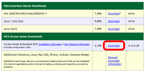
Download and install the embedded MCS kit from here. |
 |
|
|
Step 3
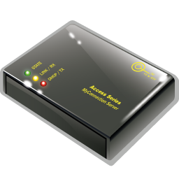
Connect the Access Series device directly to a computer using an standard RJ45 cable.
If direct connecting to a notebook the Access device will auto sense the RJ45 cable and a reverse RJ45 cable is not required.
Note that the computer used must use the same subnet IP as the Access device other than 192.168.0.98, for example 192.168.0.10 would work. |
 |
|
|
Step 4
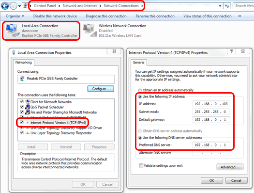
Changing the IP address and subnet differs slightly between operating systems. It is recommended to note the existing IP settings before modifying them, so they can be easily restored once the Access Series device configuration is complete.
For Windows 7 it can be accomplished as follows.
Go to the Control Panel and choose Network and Sharing Center. In the resulting screen choose Change Adapter Settings (top left). Right click on Local Area Connection and choose properties. Now click on the IPv4 option and choose properties, this will being up the dialog containing the IP settings. Change them to settings similar to those shown in step 3 above.
Click Ok once complete. This should allow the Access Series device to connect successfully. |
|
|
|
Step 5
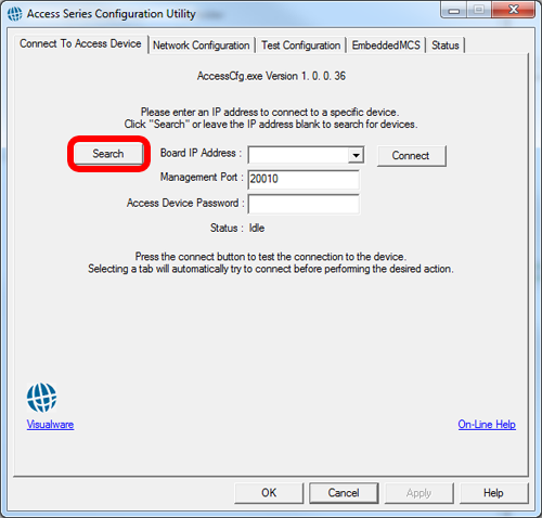
Run the configuration program by double clicking the AccessCfg.exe located in the installation directory used in step 2.
The configuration dialog will look like the example shown on the right. Clicking the search button should locate the Access Series device on the .98 address. |
|
|
|
Step 6
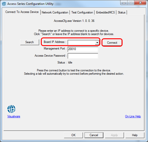
Once the device has been located the IP will appear in the "board IP address" drop down list, click "Connect" to connect to the device. A password will not be needed for new factory devices.
A password can be set at a later stage. If a password is requested then enter the password and click connect. |
|
|
|
Step 7
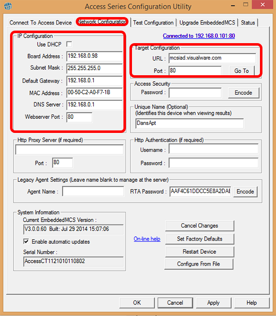
Once connected select the Network Configuration tab, as shown on the right.
The IP Configuration section holds the IP and gateway information, also shown on the right.
Uncheck the DHCP option and edit the board address and default gateway to reflect the correct values for the target network where the Access device will be connected. |
|
|
|
Step 8
The DNS server IP address, shown as Default Gateway, will also need updating to reflect the correct DNS server for the network the device is being connected to.
For most consumer or @home connections the DNS server will reflect the same IP address as the Gateway setting. |
|
|
|
Step 9
The Target Configuration section is used to specify the MyConnection Server that the Access device will connect and report to for security and management.
The password field shown in the dialog is the MyConnection Server password that manages the security of remote testing.
By default this will be set to the factory settings and will only need changing if the MyConnection Server remote testing password has been changed.
Enter the new password and click Encode. To test the MyConnection Server settings click the Go To button, this should open the
MyConnection Server menu or log-on page in a browser. Click the Apply button to save all changes. |
|
|